|
In situ stress components |
|
|
|
 |
|
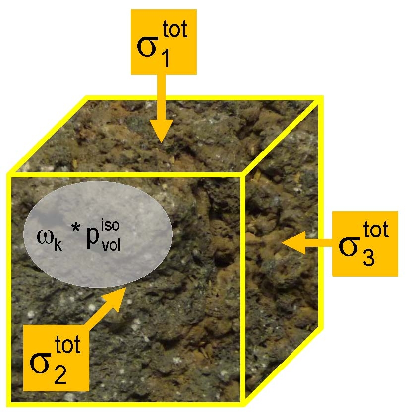
External (total) loading 
This results from the average density of the overburden, the depth, tectonic influences, the deformation properties of the rock and its degree of lateral constraint.
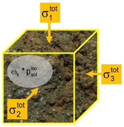
Internal loading (pore pressure) 
Pore pressure effectiveness

(3D Biot coefficient)
|
|
|
|
A consequence of the deformation properties of rock is that the hydrostatic pore pressure is generally reduced to a Mechanical Operating Pore Pressure (MOPP) as expressed by the pore pressure effectiveness (see in addition: Braun, R.: A Commonly Neglected Factor in Rock Mass and Borehole Stability. OIL GAS European Magazine, 2/2007, pp. OG79 – OG82) & Cheng, A. H.-D.: Material Coefficients of Anisotropic Poroelasticity. Int. J. Rock Mech. Min. Sci., Vol 34, No 2, S. 199-205, 1997.)
Relevant for deformation, instability and fracturing is the combination of the external loading and the mechanically effective pore pressure (MOPP), expressed as effective stress: 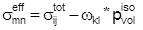
|
|
|
|
3D total in situ stresses |
|
|
|
The total in situ rock stresses are used for some rock mechanics considerations.
|
|
|
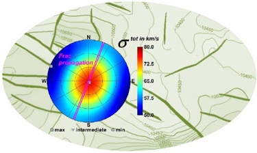 |
Rock mass structure, 3D total in
situ stresses & anticipated
direction of frac propagation
|
|
|
|
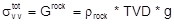
The vertical total stress component  corresponds to the weight Grock of the overlying rock layers and results from the average density ρrock, the total vertical depth (TVD) and the gravitational acceleration g: corresponds to the weight Grock of the overlying rock layers and results from the average density ρrock, the total vertical depth (TVD) and the gravitational acceleration g:
The minimum total stress component corresponds to the closure pressure of a hydraulic frac.
|
|
|
|
Stress effects of pore pressure changes |
|
|
|
Corresponding to the relation between external, internal and effective loading components  there can be changes in the effective in situ stresses there can be changes in the effective in situ stresses  resulting from the pore pressure changes. Depending on the in situ constraint conditions this can also result in variation of the total stresses resulting from the pore pressure changes. Depending on the in situ constraint conditions this can also result in variation of the total stresses . .
Because it is very difficult to predict reliably the in situ constraint conditions the two possible limits are considered.
|
|
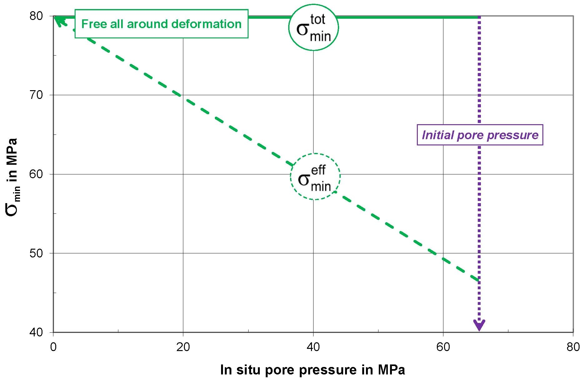
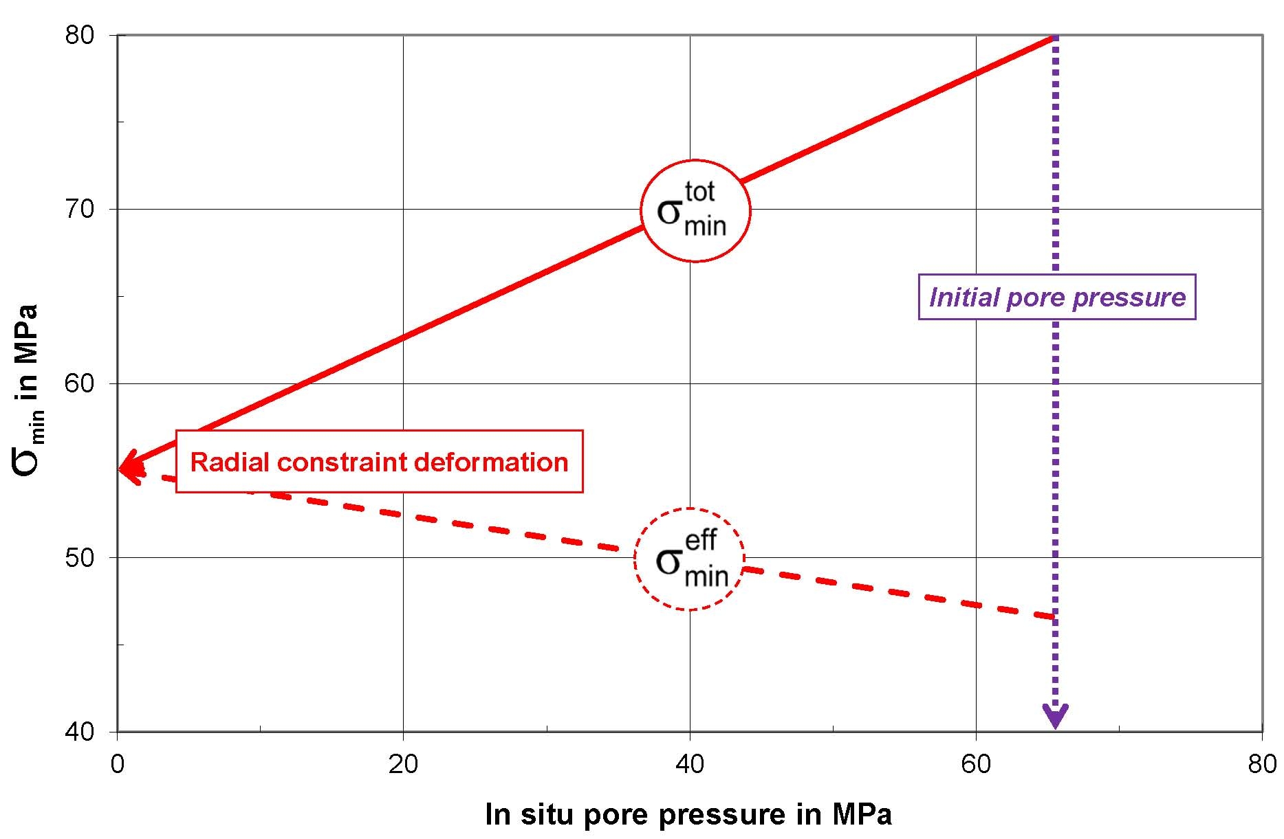
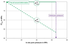
Minimum in situ stress component vs. pore pressure
|
|
|
 |

|
|
|
|
|
|
|
|
One extreme limit is free all-round in situ deformation. In such circumstances the total stresses remain unchanged ( ). ).
The changes of effective stress result directly from the change in the mechanical operating pore pressure (MOPP)
 . .
The other extreme case is complete in situ lateral constraint. In this case the changes of the effective stresses result only from the change in the vertical effective pore pressure  the freely deformable vertical direction, and from the elastic deformation properties of the rock. the freely deformable vertical direction, and from the elastic deformation properties of the rock.
In the case of a complete in situ lateral constraint of the rock mass changes occur in all the non-vertical total stresses, modifying the closure conditions (minimum total stress component) during a hydraulic frac.
|
|
|
|
Stress relaxation and sequential faulting |
|
|
|
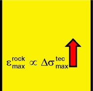
Stress relaxation and displacement can modify the configuration of principal stresses and result in a sequence of fault events.
|
| |
|
 |
|
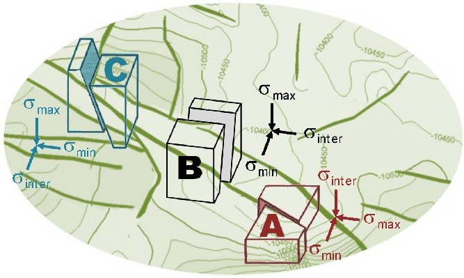
Rock mass structure, in situ stress states & faults
|
|
|
|
Possibly situations are described below:
|
A
|
Palaeo tectonic horizontal stress
component, greater than the overburden stress (
σmax = σH > σv > σh) creates a primary
strike slip fault (A).
|
|
B
|
Subsequent displacements parallel
to the primary strike slip fault (A) with a consequently relaxation of the
maximum horizontal stress component, but unmodified stress directions, creates
(because of
σmax = σv > σH > σh) a primary
normal fault (B), roughly parallel to the primary strike slip fault
(A).
|
|
C
|
Continued displacements parallel
to the primary strike slip fault (A) and the primary normal fault (B) with a
further relaxation of the primary maximum horizontal stress component
results in a stress minimum in the former maximum horizontal stress
direction and a thereby a transition of the principal tectonic stress
components. As σmax = σv > σv > σh a second (younger) normal fault (C) is formed,
roughly
normal to the primary strike slip and the first normal fault.
|
|
|
|
|
Mechanism of stress relaxation |
|
|
|
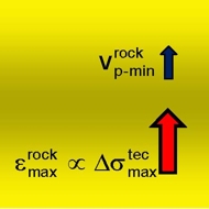
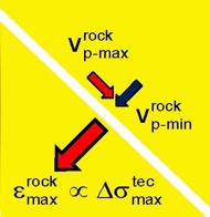
There is a direct linkage between deformations/displacements and the relaxation of tectonic in situ stress components, and this depends on the anisotropic rock behaviour, lateral constraint and compaction or displacement of fracs/faults.
|
|
Anisotropic
rock behaviour
|
|
Compaction of fracs/faults
|
|
 |
|
|
|
Lateral constraint rock mass
|
|
Displacement of fracs/faults
|
|
 |
|

|
|
|
|
Horizontal stress relaxations modify the in situ loadings and can contribute to the development of new failures, potentially with a transition to a different type of fault.
|
|
|
|
Selected procedures to determine the in situ load |
|
|
|
|
In situ
|
►
|
Crack initiation & inflow tests (Hydraulic & leak off tests)
|
|
|
►
|
Load & unload dependent
deformation (Doorstopper, overcoring - CSIRO cell)
|
|
|
►
|
Load compensation (load cell - rock
bolt, flat jack)
|
|
|
►
|
Direct stress measurement (Hard inclusion with pressure measuring encoder, borehole slotter)
|
|
|
►
|
Wave velocity analysis (crossed dipole sonic
log, focal mechanism of seismic events)
|
|
Core analysis
|
●
|
Deformation (DRA deformation rate analysis, DSA Differential
Strain Analysis, ASR Anelastic Strain Recovery)
|
|
●
|
Acoustic emission (Kaiser effect)
|
|
●
|
Elastic
wave velocity (DWVA Differential Wave-Velocity Analysis, WVA Wave
Velocity Analysis, RACOS®)
|
|
|
|
|
Rock stresses can also be calculated (amongst others with the concept "In situ stress limitation") on the basis of known data and observations (overburden pressure, breakouts, induced fracture in the borehole wall, core discs, etc.).
|
|
|
|
Comparison of different in situ stress analysis procedures |
|
|
|
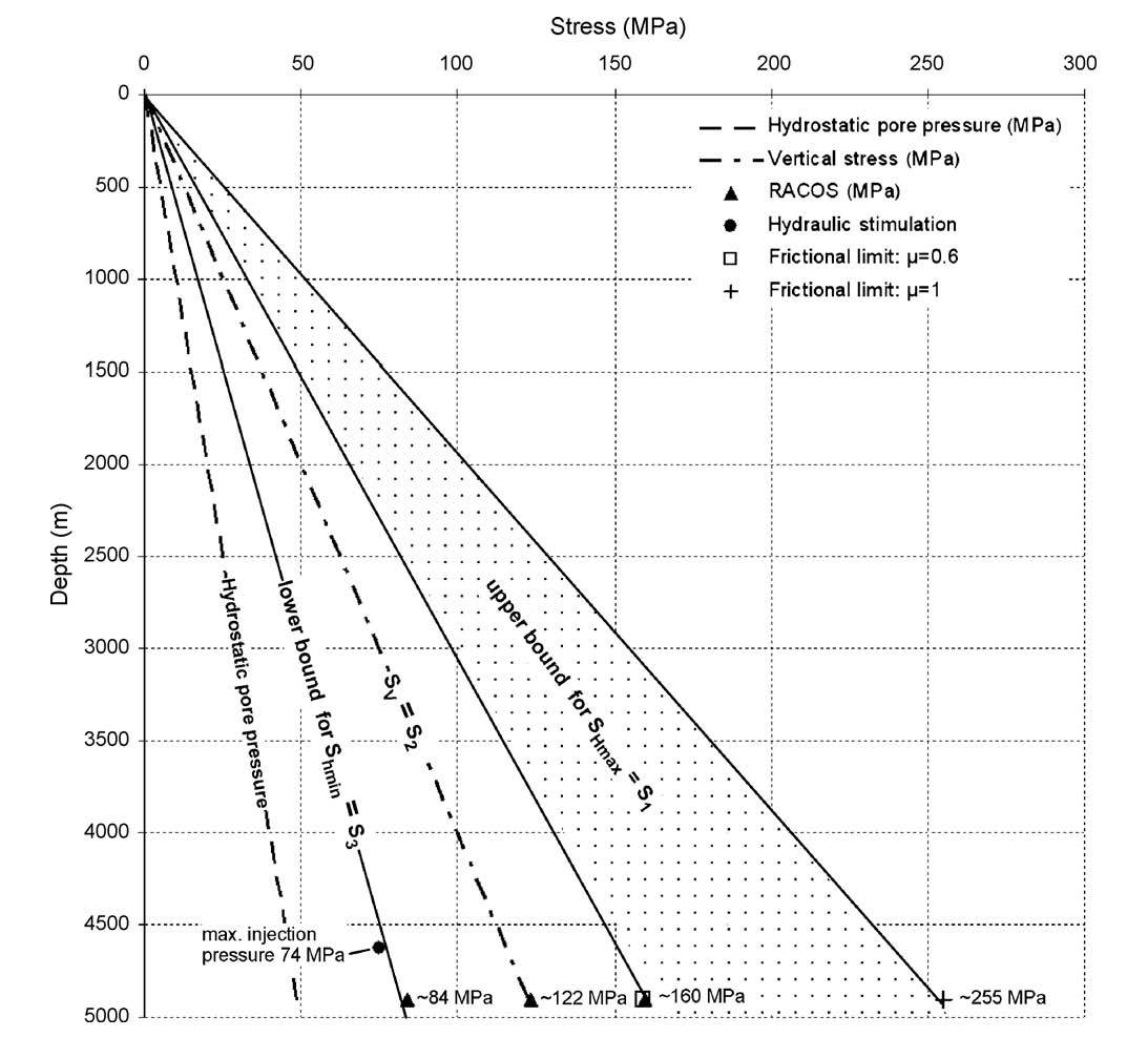
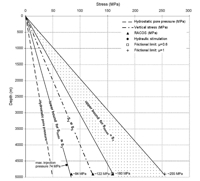
As a comparison of different in situ stress analysis procedures, results are shown below for 3 common methods applied to the same task are cited (borehole Basel 1 in a depth range between 4500 - 5000m).
Used analyses methods:
|
►
|
Hydraulic tests (direct In situ estimation of the minimum rock stress component)
|
|
►
|
RACOS® (direct estimation of all the 3D in situ stress components withcore analysis)
|
|
►
|
In situ stress limitation (specific rock observations and involved calculations)
|
Häring, M.O. et al.: Characterisation of the Basel 1 enhanced geothermal system. Geothermics (2008)
|
| |
|
 |
|
Constraints on Shmin and SHmax in the well Basel 1, deduced from hydraulic data, RACOS® (Braun 2007) and the concept of in situ stress limitation (Zoback 2007); Sv was calculated by the integration of wire line density logs - [see Fig. 4 in Häring et. al. (2008)].
|
|
|
|
 |
|
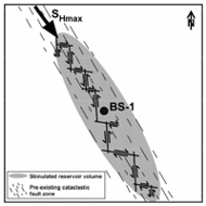
Schematic model of reservoir development in an assumed pre-existing cataclastic fracture zone. Fault plane solution of medium to large events indicate that frictional sliding has been induced on roughly NS- and EW-trending structures that are ordered in an en echelon like arrangement (BS-1: well Basel 1) - [see Fig 13, bottom panel in Häring et.al. (2008)].
|
|
|
|
Braun, R.: Analyse gebirgsmechanischer Versagenszustände beim Geothermieprojekt Basel (2007)
|
|
 |
|
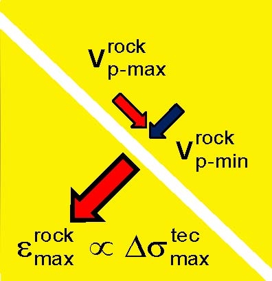
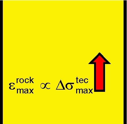
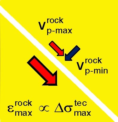
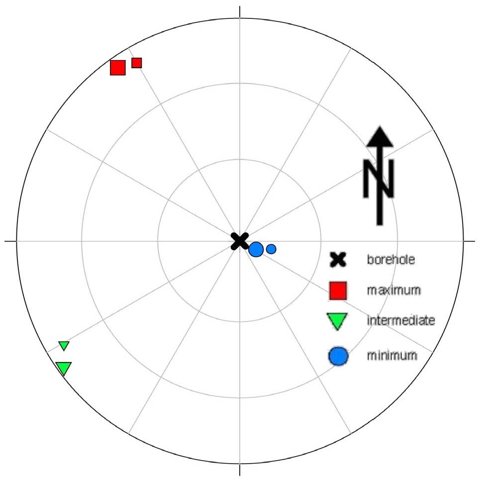
Geographical orientation of the tectonic principal stress components for laterally unconstrained rock (large symbols) and for laterally constrained rock (small symbols) - [see Fig 2.3, bottom panel in Braun (2007)].
|
|
The comparison of the results of stress analyses in an identical location shows the compatibility of different methods. If there is a drill-core available, RACOS® is the best choice. It allows the direct determination of the complete (3D) recent and palaeo rock stress tensors. In addition, it provides information about the rock mass structure, the tectonic stress components, deformations, and in situ stress changes resulting from pore pressure changes.
|
|