|
Factors in the rock mass that influence the borehole stability |
|
|
|
|
|
|
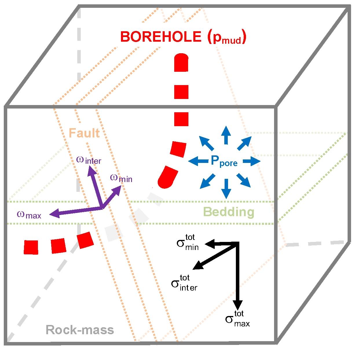
Loading conditions
|
|
 , ,
 , ,

|
Total in situ stresses
|
|

|
Pore pressure
|
|
 , ,
 , ,

|
Pore pressure effectivenesses
|
|

|
Mud pressure (in the borehole)
|
|
|
|
Further relevant factors |
|
|
|
●
|
Borehole wall condition (permeable, impermeable, or cased)
|
|
●
|
Orientation of the borehole and of perforations
|
|
●
|
Orientations and properties of faults and bedding planes
|
|
●
|
Deformation properties and strength of the surrounding rock
|
|
|
|
|
|
Stresses around a borehole |
|
|
|
|
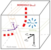
Primary in situ
stress state
|
|

|
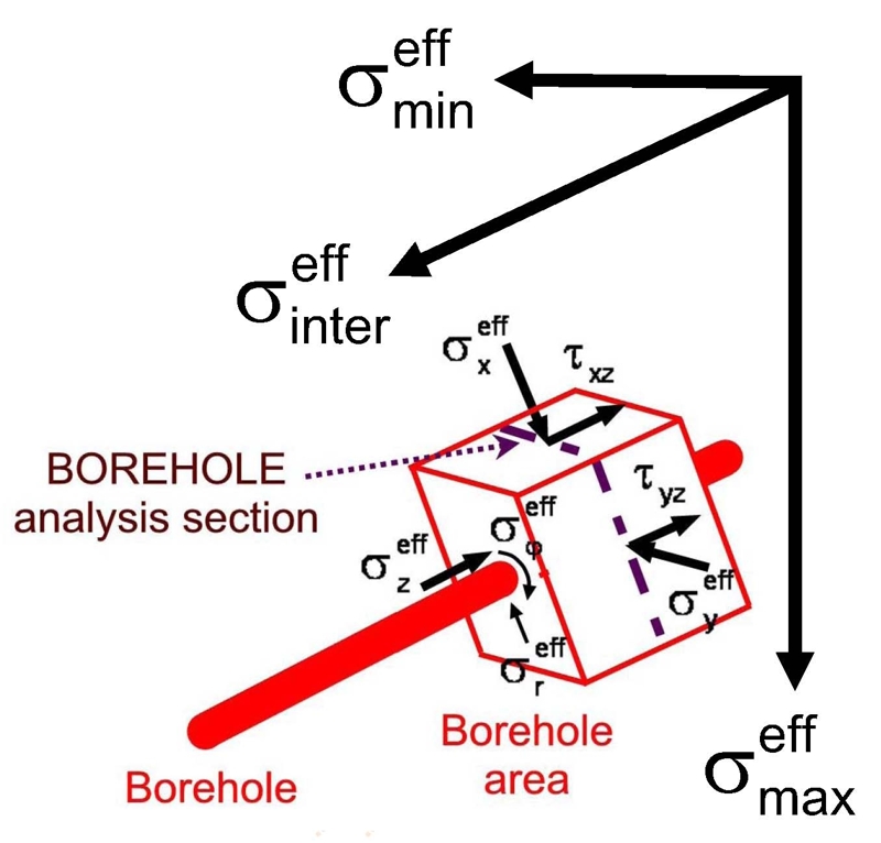
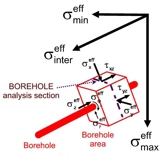
Effective stresses
in the rock mass
|
|

|
Effective stresses
parallel and perpendicular to the borehole axis
|
|

|
Shear stresses parallel
to the borehole axis
|
|
Secondary stress
state around openings
|
|

|
Effective stress
radial to the borehole wall
|
|

|
Effective stress
tangential to the borehole wall
|
|
|
For a borehole aligned parallel to an in situ principal effective stress the normal
stresses perpendicular and parallel to the borehole alignment are identical
with the effective principal stresses in the rock mass and there are no
shear stresses in that direction.
For a boreholealignment deviated from the orientations of the in situ principal
effective stresses results in different magnitudes and orientations of the
normal stresses in relation to the borehole and in shear
stresses parallel to the borehole axis.
A modified borehole
orientation can result in a different failure mechanism. |
|
|
|
3D Stress configuration and strength (GLAST) |
|
Description of the
load dependent strength with the Mohr-Coulomb criterion
|
|
|
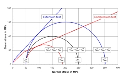 |
Compression test ( ) )
→ too
pessimistic
Extension test ( ) )
→ too optimistic
|
|
|
|
Description of the load dependent strength with the Tauber criterion
|
|
|
|
|
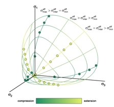 |
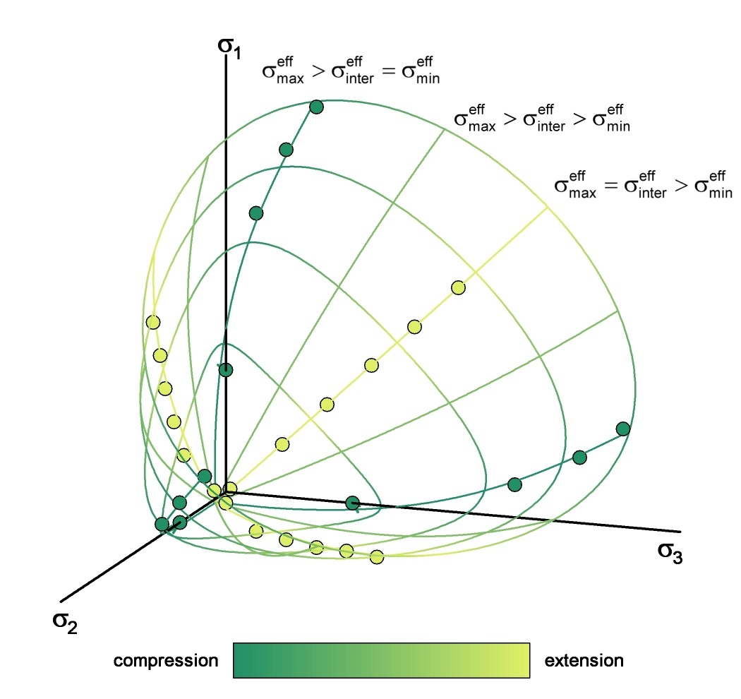
Collation of the strengths under any 3D stress states in an envelope surface (characterized
with only three parameters).
The strengths used to
define the failure envelope are determined in compression & extension
tests.
|
|
|
|
Use of
the classical Mohr-Coulomb rock strength criterion for borehole stability
analyses can result in considerable reduction of the reliability assessment;
the Tauber failure criterion defines the strength under 3D stress
conditions (GLAST), which largely excludes the uncertainty in many current
assessment approaches.
|
|
|
|
Identifying zones of instabilities |
|
|
|
|
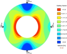 |
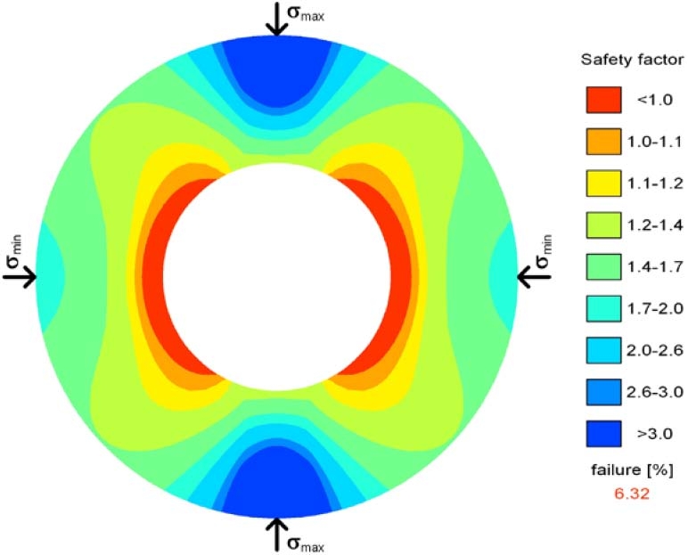
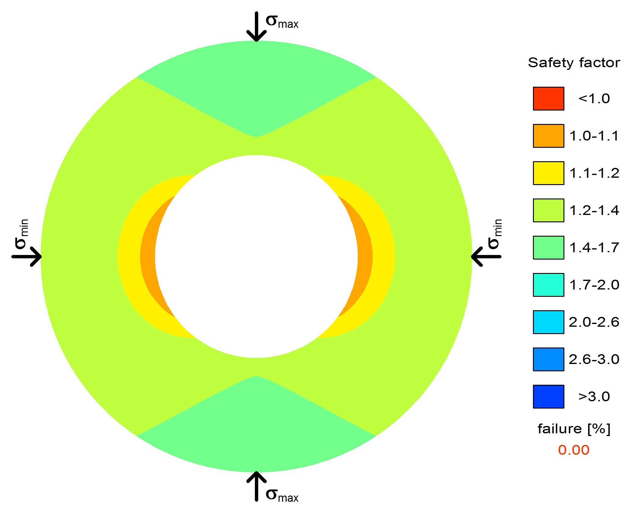
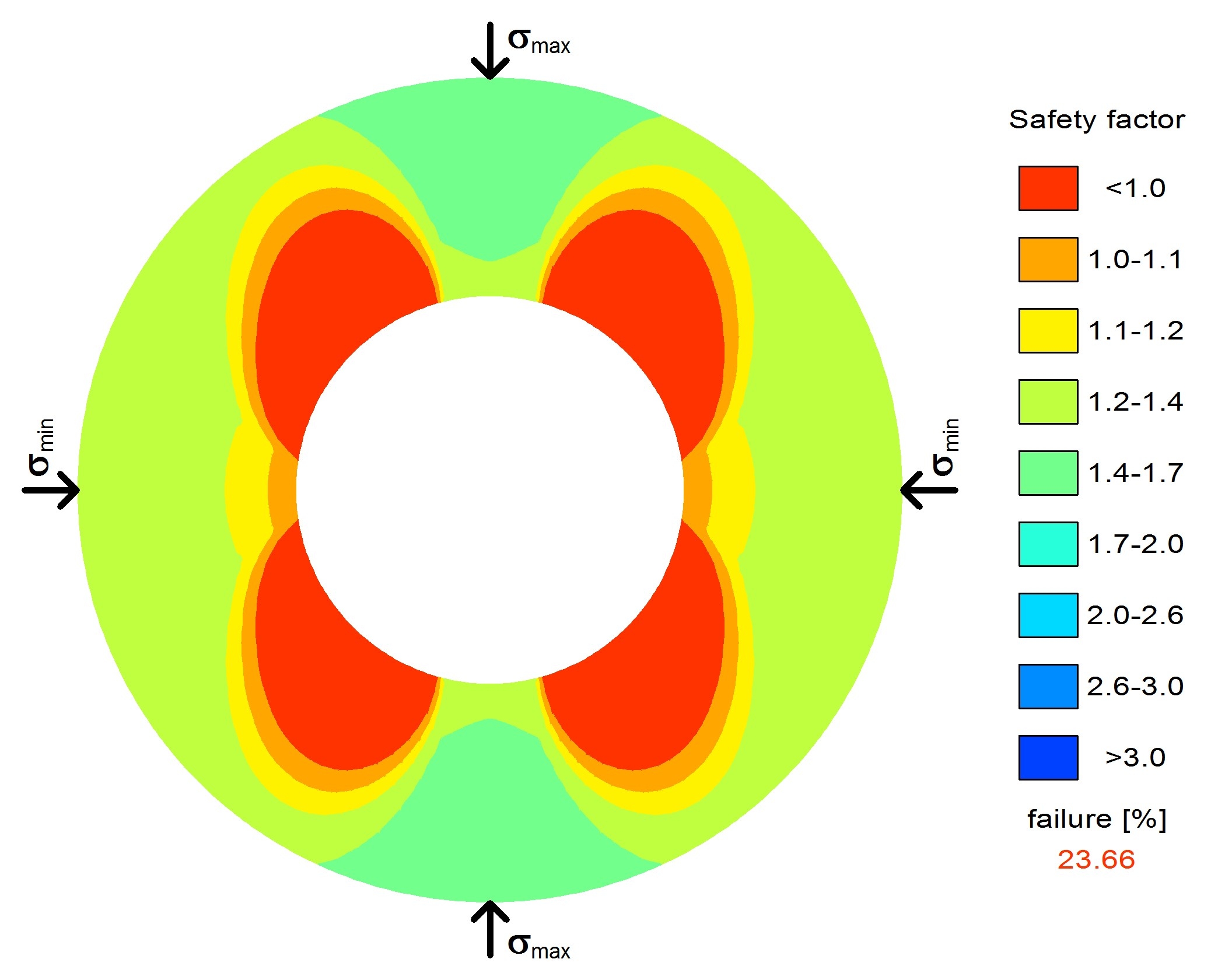
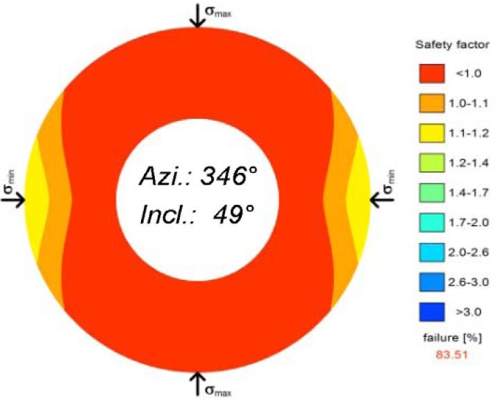
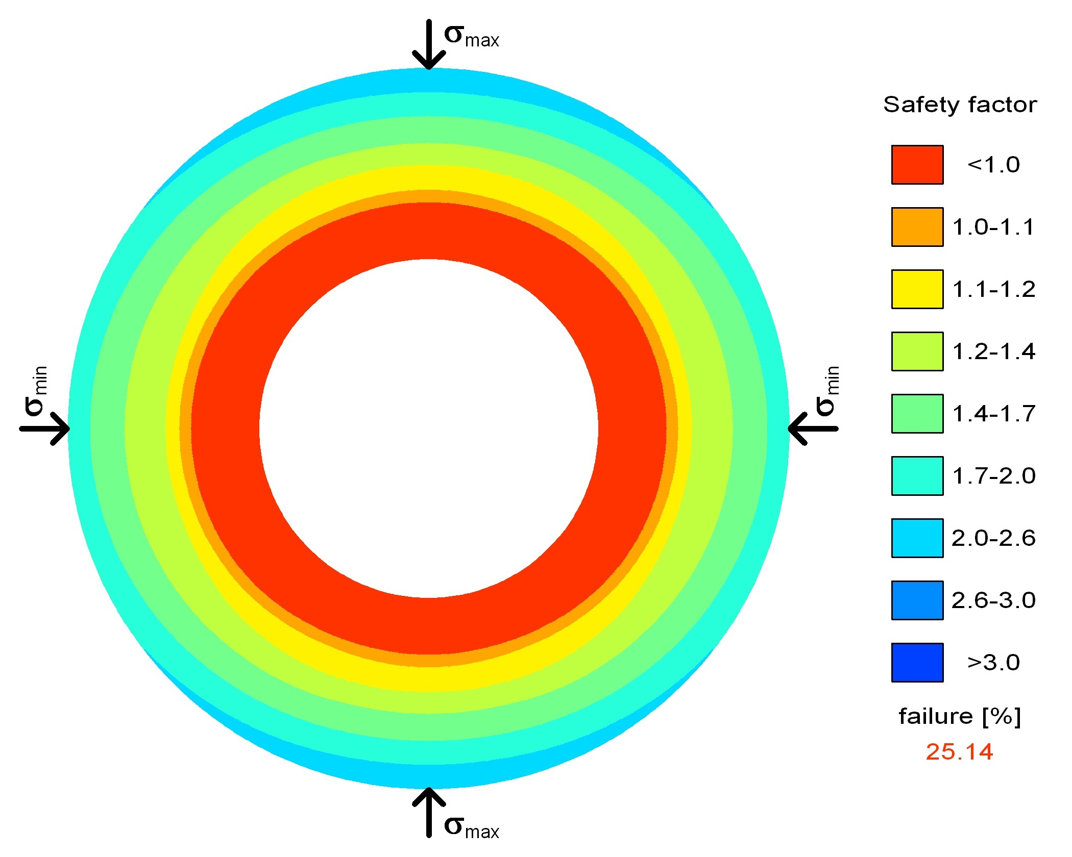
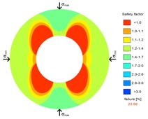
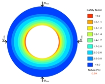
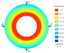
The relative positions
of the failure envelope and the current 3D stress state define the Safety
Factor.
A Safety Factor ≤ 1 shows that the strength has been reached or exceeded and this could mean that macroscopic failure/sanding occurs in that region.
|
|
|
|
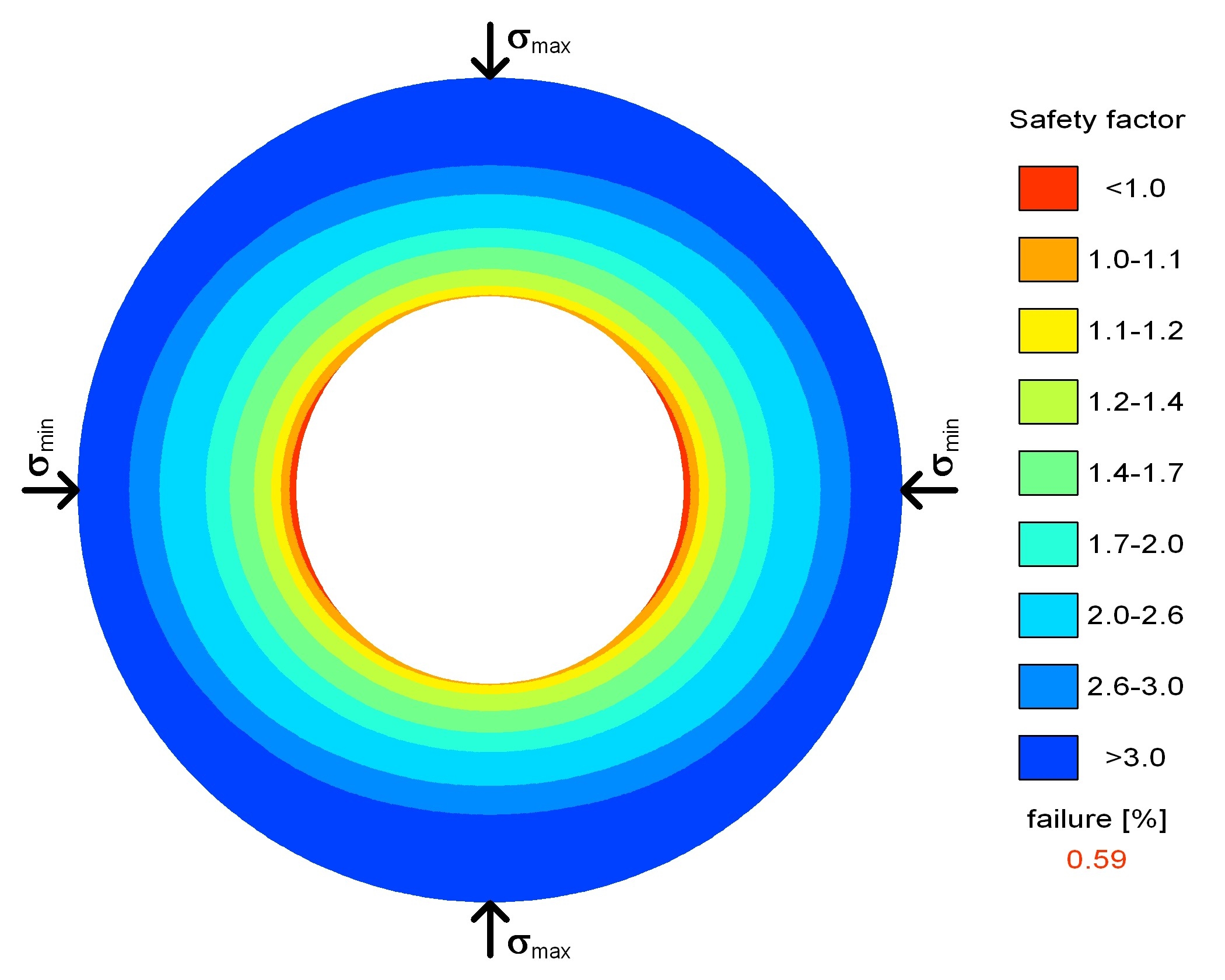
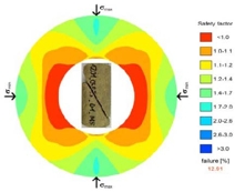
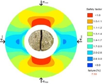
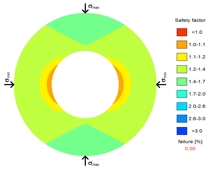
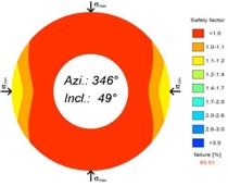
The
overall stability assessment around the borehole is illustrated with a
colour corresponding to the Safety Factor. This shows the radial and
tangential extent of unstable regions.
Special
evaluations of the stress conditions around the borehole wall, and of their
3D orientations, are used to assess the type of failure.
|
|
|
|
Common types of failure |
|
|
|
|
 |
Breakout (shear failure)
Cause: Critical normal stress deviator around the borehole wall.
Propagation: Usually in the direction of the minimum, but possibly also in the direction of the maximum far field stress component perpendicular to the borehole axis.
|
|
|
|
|
 |
Frac (tensile failure)
Cause: Critical tangential tensile stress in the borehole wall.
Propagation: In direction of the maximum far field stress component perpendicular to the borehole axis, with the minimum stress component as the frac surface normal.
|
|
|
|
Influence of planes of weakness on the borehole stability |
|
|
|
Borehole in undisturbed rocks
|
Borehole parallel to a plane of weakness
|
|
|
 |
|
|
|
|
Borehole trajectories closed to or parallel to the orientation of zones/planes of weakness increase the risk of instabilities.
|
|
|
|
Causes of failure in deviated boreholes |
|
|
|
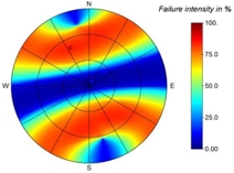
Trajectory & failure intensity
|
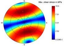
Trajectory & shear stresses
|
|
|
 |
|
|
|
|
Instabilities in boreholes deviated from a principal stress axis can result from critical shear stresses parallel to the borehole axis, especially in the direction of the largest difference between the maximum and minimum far field stress components.
|
|
|
|
Effects of shear stresses parallel to the borehole axis |
|
|
|
|
 |
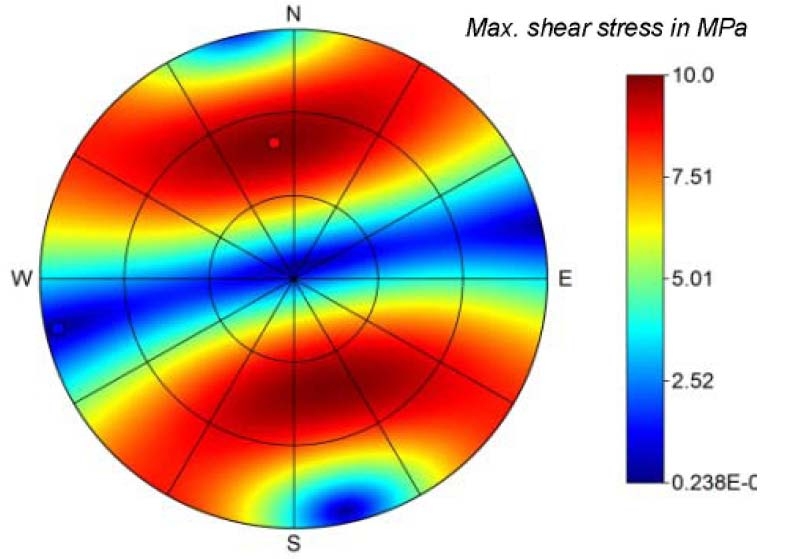
Critical
shear stresses parallel to the borehole wall result in breakout &
peeling.
A critical normal stress deviator is not necessarily required.
|
|
|
|
3D in situ stress state and borehole stability |
|
|
|
|
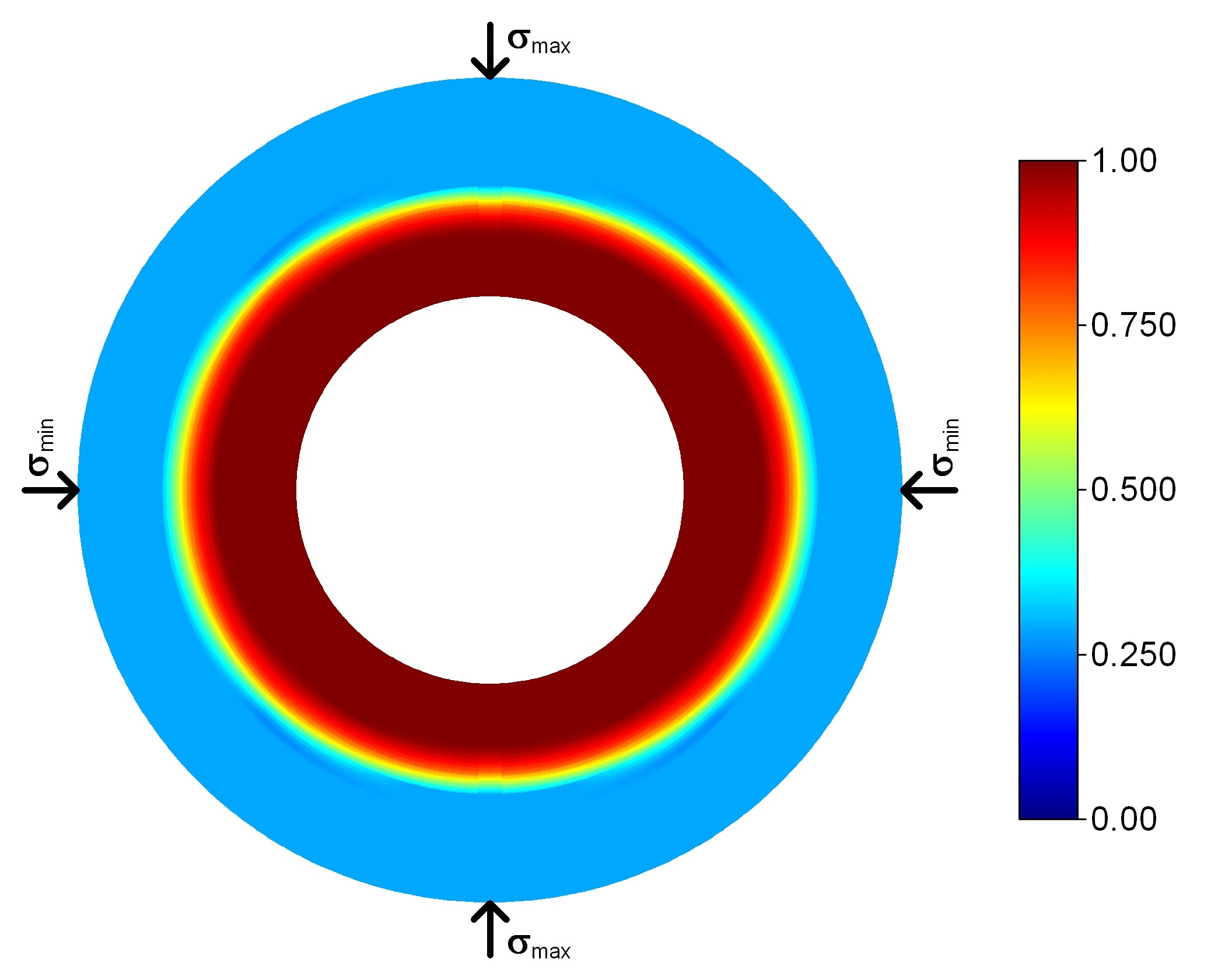
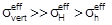
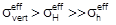
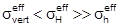
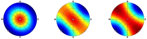
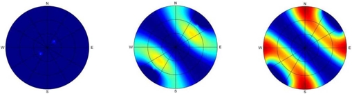
Spatial effective stress
magnitudes (dark blue → min, dark red → max)
|
|
|
|
|
|
|
 |
|
|
|
|
Failure intensity in the near
borehole zone (dark blue → min, dark red → max)
|
|
|
 |
|
Different intermediate principal stress magnitudes, even with unchanged maximum and minimum stress components, can lead to very different failure intensities.
|
|
|
|
Failure affected by MOPP+
(see 3D Biot coefficient) |
|
|
|
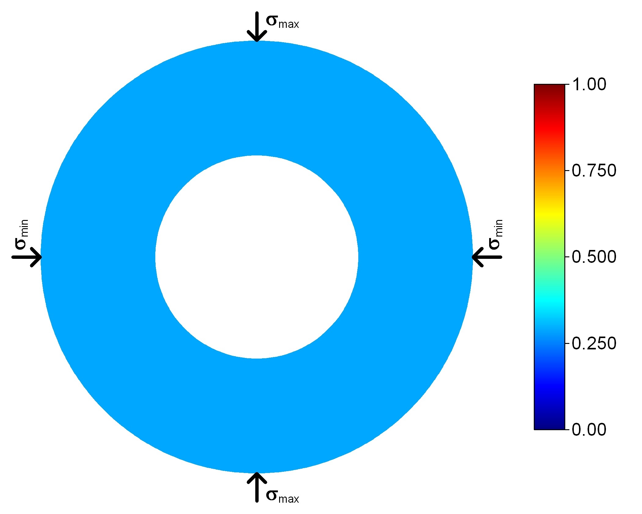
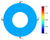
Initial pore pressure effectiveness
|
Initial borehole stability
|
|
|
 |
|
|
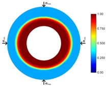
MOPP+ & pore pressure effectiveness
|
MOPP+ & borehole stability
|
|
|
 |
|
|
|
Loosening, particularly in low porosity rocks, increases the pore pressure effectiveness (MOPP+), and thus changes the effective stresses. This can lead to a time-dependent propagation of failure and to increasing borehole instabilities..
|
|
|
|
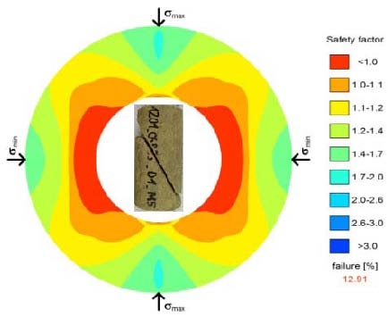
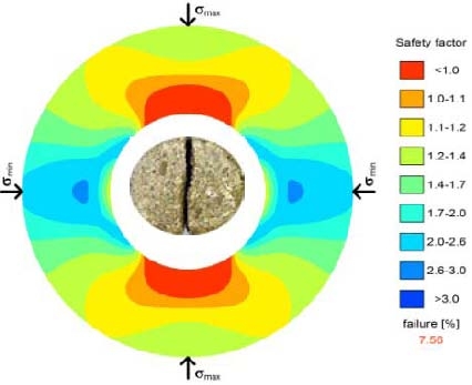
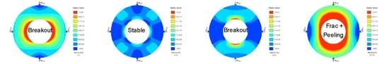
Optimization of drilling parameters (e.g. mud pressure) |
|
|
|
low
|
optimal
|
high
|
very high
|
|
|
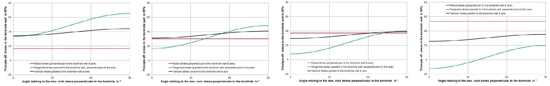
Stress in
the borehole wall (red - radial stress,
green - tangential stress , black - paraxial stress)
|
|
|
|
|
Stability around the borehole (red - Zone of instability)
|
|
|
|
|
With an appropriate collation of individual stability analysis results, further analyses can be made of the trend of the development of instability (for example resulting from varying mud pressure, borehole alignment, etc.).
|
|
|
|
Summary of borehole stability |
|
|
|
The borehole stability is (in addition to technical and technological parameters) affected by rock mechanical boundary conditions. They have very different, partly opposing effects with respect to the risk of failure. But this can be evaluated with expert rock mechanics analyses, and can therefore be mitigated.
|
|